
One common algorithm to perform Face Morphing requires fitting a polygonal mesh on top of all input face images. This must be done in a way such that each vertex converge to the same physical spot of all faces – such as the eye contour, nose tip, chin, etc. Having such a mesh aligned to a face can also be useful for other purposes, from caricaturing to beautification, by performing non-rigid modifications to the original face.
In this post, I’ll describe how I implemented a simple face distortion tool using only JavaScript and HTML5.
Triangle deformation
First, let’s describe how a single texturized triangle can be deformed when its vertices are repositioned.
Let A, B and C be the original triangle vertices, and A’, B’ and C’ be the repositioned triangle vertices. Also let p be the euclidean coordinates of a point inside this triangle. We know that this point can also be described by the barycentric coordinates <α, β, γ>. By making the euclidean coordinates p’ of the equivalent point in the triangle A’B’C’ have the same barycentric coordinates, we can compute
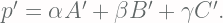

Since 

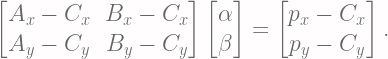
This can be modeled in matrix form, as follows:
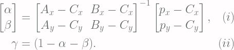
Finally, the barycentric coordinates can be found by the following equations:
At this point, it is clear that using barycentric coordinades to deform single triangles works well and efficiently (as the inverse of the 2×2 matrix doesn’t need to be performed for each coordinate p’, since it only depends on the triangle vertices). Now we need to make sure that this idea will work well when we have multiple triangles composing a mesh.
This will only work if the transition between neighboring triangles is continuous. For this condition to be satisfied, the barycentric coordinates at the triangle edges must only depend on the vertices that belong to that edge.
For instance, the barycentric coordinates for any point lying in the edge A’C’ must only depend on the vertices A’ and C’. Happily, this condition is also satisfied by the barycentric coordinates. As an example, let’s consider the points lying in the edge A’C’. These points can be expressed as 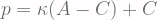

Modeling a facial mesh
Now that we have the mathematical framework to deform a mesh, it is important to consider the symmetrical nature of the human face before modeling the facial mesh.

For the implemented demo, I also considered a set of triangles around the edge of the subject face (shown highlighted in the figure above). This set exists to allow for editing the face contour without introducing discontinuities between face and background.
JavaScript implementation
User Interface
The JavaScript demo developed for this article was created without any third party libraries, as the objective was to produce a minimal demo without external dependencies. The handles that control the triangle shapes have their mousedown, mousemove and mouseup events sent to a UI Manager object that has the following finite state machine:

By using the observer design pattern, the Triangles are decoupled from the UI Manager object by subscribing to the move event of each one of its vertices, which is raised by the UI manager when it is in the Moving State and receives a mousemove event from a handle. This is illustrated by the sequence diagram below.

Treating the Mesh Contour
The outermost vertices of the mesh (and, consequently, its outline) is intentionally hidden from the user to prevent the introduction of discontinuities in the reshaped image, which would happen if the user moved these vertices. To this end, we need to determine which vertices belong to the outline of the mesh, so they can be hidden from the user.
This is accomplished by the following algorithm. We start with a set 


This algorithm finds the mesh contour because any edge that is not part of the outline will appear twice in our iteration (since they belong to two neighboring triangles), and therefore will be added and later removed from C. Edges at the contour, however, will appear only once, and therefore will not be removed from C. Note that this algorithm is very efficient, since it has time complexity O(n).
Final thoughts
When modeling the face in the demo tool, you may have noticed that corners may arise when distorting polygons containing visible edges. This is due to the fact that the derivative of our distortion model is not continuous, although the distortion model itself is.
In other words, the barycentric model is of class C⁰, but not C¹. This means that a single straight line may become multiple continuous straight lines when a triangle is distorted, and its corners will be located at the boundary between the triangles containing the moved vertices.
This can be improved by using C¹-continuous deformation models. Keep in mind that such methods are also subject to having downsides. For instance, they may extend the region of influence of each vertex to other neighbor triangles, which could result in unwanted deformations; furthermore, their computational cost may also be higher.
